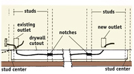
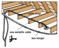
|
Create New Account
Millard Lumber Newsletter
Register to receive newsletters and notices by email. Register Now
|
Adding Electrical Wiring
Use these tips and instructions for adding new electrical wiring. Take a few minutes to read the directions thoroughly. Following these instructions can save you time and effort and ensure a safe installation.
|
FIG. 1 - Basic principles
of good wiring.
|

BASIC PRINCIPLES OF GOOD WIRING
- Before beginning any electrical repair, shut off the power. Remove
the fuse or trip the breaker for the circuit you will be working on
in your service panel. Use a neon tester to be sure the power is off.
If there is any doubt, you can remove the main fuse or trip the main
breaker. Remember: Removing the main fuse or tripping the main breaker
will usually shut off the power to the entire house.
- Electrical wires are color coded to prevent wiring errors.
- White wires almost always connect to other white wires or to chrome terminal
screws on switches and receptacles.
- Some wiring devicessuch as receptaclesare back-wired by pushing
the bare wire end into spring grip holes. These wiring devices are plainly
labeled to show which color goes into each spring grip hole.
- Switches are nearly always connected into black wires in cables. The only
exception is where a cable is extended, making it necessary for the
white wire to play the role of the black wire. When this is necessary,
the white wires should be painted black to prevent future wiring errors.
- Study the wiring diagram in Fig. 1. This will help you understand the basic
principles of good wiring. Also, find a good electrical how-to book.
It's one book every homeowner should keep on hand for ready reference.
- Most home wiring is complete with either No. 14 gauge or No. 12 gauge wiring.
No. 14 is the smallest wiring permitted under most codes.
- Always use the same size cable for a continuation of any extended wiring circuit.
|
|
FIG. 2 - Attach the
new wiring to the unused screws on the device in the last receptacle.
|

CONNECT NEW WIRING TO LAST OUTLET IN CABLE
- New wiring should be connected to the last outlet in a run of cable. To
locate the last outlet in the run, shut off the current. Remove the
cover plates from each outlet on the circuit. The last outlet in the
run has wires connected to only two of the four terminal screws (Fig.
2).
- The two unused terminal screws on the last receptacle serve as a starting point for wiring to a new outlet.
|
|
FIG. 3 - The diagram
illustrates how to continue wiring from the last receptacle in a wiring
run.
|

ATTACHING CABLE FOR NEW WIRING
- Shut off the power to the circuit you will be working on at the service
panel.
- Loosen the screws holding the receptacle in the box and remove it, as shown
in Fig. 2.
- Attach the white wire to the chrome terminal, the black wire to the brass
terminal on the receptacle and to the box, if the box is metal.
- Use care to match the size of the original cable. If No. 12 wire is used,
continue with No. 12. If No. 14 wire is used, use No. 14 for continuing
the cable. The size of the cable is usually stamped on the side of the
cable.
- New wiring can be connected to continue the run beyond the last receptacle (Fig. 3). Note that the new wires are pulled through knockout plugs in the back of the outlet box.
|
|
FIG. 4
|

ADDING NEW WIRING FROM A JUNCTION BOX
- New wiring can also be tied into a junction box, unless the wiring in the
junction box is already at maximum capacity.
- Before tying in at a junction box, always trace the cables leading to the
box to check the voltage. Be sure you are not connecting a 120-volt
outlet to a run of wire providing 240 volts for larger appliances.
- To tie in new wiring at a junction box, first shut off the current at the
service panel.
- Locate the main supply cable coming into the junction box from the service
panel. Locate the supply wire by tracing the white wires. All white
wires in the junction box will be attached to the white wire on the
supply line (Fig. 4).
- Knock out the unused plug on the junction box and run the new line from
the box as illustrated (Fig. 4). Be sure to use a cable clamp to secure
the cable to the junction box.
|
|
FIG. 5 - New wiring
can be tied in at a ceiling light when the light is not switch controlled.
|

TYING IN NEW WIRING AT A CEILING LIGHT
- You can tie in new wiring at a ceiling light if the light is not controlled
by a switch.
- Shut off the current at the service panel.
- Tie white wires to white wires and black wires to black wires, as illustrated
in Fig. 5.
- Connect the ground wires as illustrated. If you are using a metal box,
attach them to the box as well as the light fixture.
- Knock out an opening in the outlet box, and continue the new wiring as illustrated.
|
|
|

ALWAYS MATCH CONNECTORS TO
TYPE OF CABLE USED
- Some boxes come with built-in connectors.
- Armored cable connectors have inner rims to hold fiber bushings at the
end of the cable.
- Nonmetallic cable connectors are designed to grip the installation around
the cable with a two-screw clamp.
- Regardless of the type of cable used, always leave about 6" to 8"
of wiring in the box to allow plenty of wire for making easy connections.
- You can tighten the nut on either type of cable connector by placing a screwdriver in the notch and tapping the screwdriver lightly.
|
|
FIG. 6 - All connections
must be made in an approved box.
|

MAKE ALL CONNECTIONS IN APPROVED BOXES
- Always remember that connections must be made in an approved box (Fig.
6). Never connect one cable to another by an open-line splice.
- All switch, outlet, and junction boxes must be positioned so they are always
accessible.
- You can easily remove knockout plugs with a nail punch, screwdriver or
metal rod.
|
|
FIG. 7 - Drill a hole
through the floor and run the cable to the new outlet.
FIG. 8 - The new cable
can be pulled though with a string, weight and wire.
FIG. 9 - Cable can
be run from one outlet to another.
|

RUNNING NEW CABLE BETWEEN MULTIPLE FLOORS
- Drill a hole through the floor from bottom to top, as illustrated in Fig.
7. Be sure the hole is drilled into the recessed area behind the wall
rather than in the open. Be sure to use a bit that's large enough to
permit free passage of the wiring cable.
- Run the cable through the newly drilled hole to the desired location
for the new receptacle or switch (Fig. 7).
- Bring the cable through the opening by using a weight on the end of a string
and a wire with a hook on the end (Fig. 8).
- Using this same technique, you can add one outlet to another by drilling up through the floor, pulling the cable under the floor, and then running it to the desired position on the opposite wall (Fig. 9). The same wiring can be pulled through for either receptacles or switches.
|
|
FIG. 10 - It is often
easier to add new cable from ceiling boxes.
FIG. 11 - Cable can
be "fished" through with special fish tape.
|

ADDING NEW WIRING FROM BOXES IN CEILING
- If your home has an unfinished attic, it may be easier to add new wiring
by attaching it to boxes in the ceiling (Fig. 10). In this way, gravity
works for you rather than against you.
- Attach the cable to the box as previously described.
- Cut a hole in the wall at the desired location for the switch or receptacle,
and run the cable from the box in the ceiling to the new outlet location
(Fig. 10).
- Bring the new cable through the wall and ceiling by cutting and drilling holes in and through the wall, the 2x4 plate, and the ceiling (Fig. 11). A special fish tape is available for these types of jobs.
|
|
FIG. 12 - New cable
can be run along the baseboard to a new outlet.
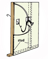
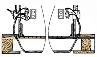
FIG. 13 - Cut an opening
in the wall opposite the existing box.
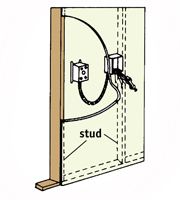
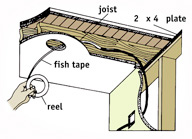
FIG. 14 - If the new
box is not near a stud, it can be held in place by box supports.
|

ADDING NEW WIRING ON THE SAME WALL
- You can connect new cable from an existing outlet to a new outlet on the
same wall by running it inside the wall (Fig. 12). Mark the approximate
location of the new outlet. Using a stud finder locate and mark the
wall studs. Start one stud before the existing outlet and end one stud
after the new outlet.
- Mark the exact location of the new box. Make it the same height as the
existing box. Do not locate it over a stud. Using a drywall or keyhole
saw, cut the opening for the new box.
- Using a utility knife and a drywall saw, cut a strip of drywall about 3"
wide out of the wall, below the outlets. Start at the center of the
first stud you marked and end at the center of the last stud; watch
for nails as you cut. Carefully remove the drywall strip.
- Using a hand or circular saw, make two cuts 1" apart and 3/4"
deep in each of the exposed studs. Using a hammer and a chisel, remove
the wood between the two saw cuts.
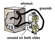
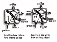
- Be sure the power is off to the existing outlet. Remove the cover
plate and the receptacle. Remove one of the knockouts in the bottom
of the box. Run the new wire behind the wall and up through the knockout
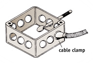
in the box. Tighten the clamp and attach the wires. If the box does
not have a clamp, place a wire clamp on the new cable. Tighten the screw
to hold the clamp on the wire. Be sure the nut is off the wire clamp
and run the wire up to the box as before. Feed the threaded end of the
clamp up through the knockout, replace the nut and tighten. Replace
the receptacle and the cover plate.
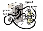
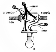
- On the new box, remove one of the knockouts in the bottom of the box. If
the box you are using is a self-clamping box, insert the box into the
wall and tighten. If not, insert the box into the wall, insert a Madison
hanger on each side of the box, and bend the tabs over into the box
to tighten.
- Finish running the wire from the existing box through the notches and up
behind the wall into the box as before. Clamp the wire and install the
receptacle as in Fig. 3. Install the cover plate, turn on the power,
and test the circuit with a neon tester. Shut off the power again to
safely finish the project.
- Nail metal cable protectors to the exposed studs over the notches. Replace
the drywall strip you removed earlier. Use the spackling compound and
drywall tape to complete the installation.
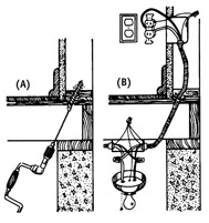
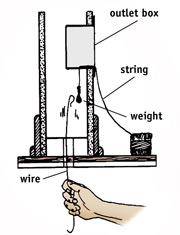
- Cable can be pulled from an existing box on one wall to a new outlet on
the opposite side of the same wall (Fig. 13).
- Attach a cable to the existing receptacle in the box as previously
described. Allow ample slack in the cable to permit easy connection
to the new box to be installed on the opposite wall.
- Bring the cable through the new opening with a wire, as illustrated in
Fig. 13.
- Connect the cable to the new box, attach the desired receptacle, and mount the box to the wall with box supports if it is not near a stud (Fig. 14).
|
Check your state and local codes before starting any project.
Follow all safety precautions. Information in this document has been furnished
by the National Retail Hardware Association (NRHA) and associated contributors.
Every effort has been made to ensure accuracy and safety. Neither NRHA, any contributor
nor the retailer can be held responsible for damages or injuries resulting from
the use of the information in this document.
|